The Arduino Environment
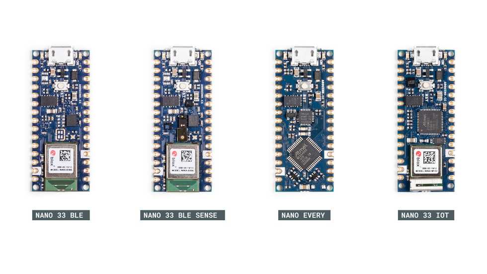
- Arduino Nano 33 IoT
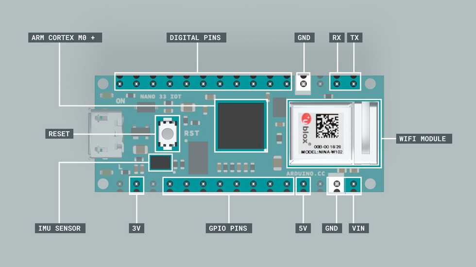
- ARM Cortex M0+
- Wifi module with a crypto-chip to ensure secure communication
- Can be configured to constrain its power consumption to keep it running for long periods
Board Hardware
- ARM Cortex M0+
- 32 bit chip
- low-cost
- lowest power requirements of all the Cortex-M processors
- Allow developers to optimize power usage for specific applications
- IME Sensor
- 3D digital acelerometer
- 3D digital gyroscope
- 1.25mA
- Wi-Fi Module: Nina W102 Wifi module
- Multi radio
- Integrated antenna
- Wifi and bluetooth
- IoT
- Digital and Analog Pins
-
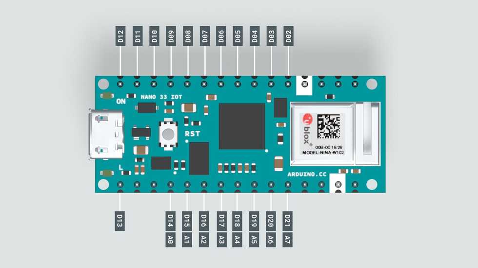
- 19 Digital Pins marked as D2-D21
- Digital pins can transmit values of 0 OR 3.3V, relative to GND
- Or can receive data, the voltage is interpreted as HIGH or LOW, relative to some threshold between 0 and 3.3V
- 8 Analog pins, A0-A7.
- Analog pins can transmit or receive voltage values between 0 and 3.3V, relative to GND
- D14-D21 or A0-A7 can both transmit and receive voltage values and there are also called General purpose Input/Output(GPIO) pins.
- Never apply more than 3.3V to pins of Arduino Nano 33 IOT
-
- GND, 5V, 3V, VIN
- GND, 5V and 3V are reference valtage lines
- VIN pin can be used to provide poser to the board from an external battery source
- RX/TX
- Used for communication between the Arduino board and a computer or other devices
- All Arduino boards have at least one serial port (also known as a UART or USART), and some have several. It communicates on digital pins 0 (RX) and 1 (TX) as well as with the computer via USB. Thus, if you use these functions, you cannot also use pins 0 and 1 for digital input or output.
- I2C
- Inter-Integrated-Circuit is a bus-based serial communication protocal that happens using two signal pins: SDA(data signal) and SCL (clock signal)
- This protocol allows you to connect several devices to the same lines (SDA and SCL) and each device is selected by calling its unique address identifier.
IDE
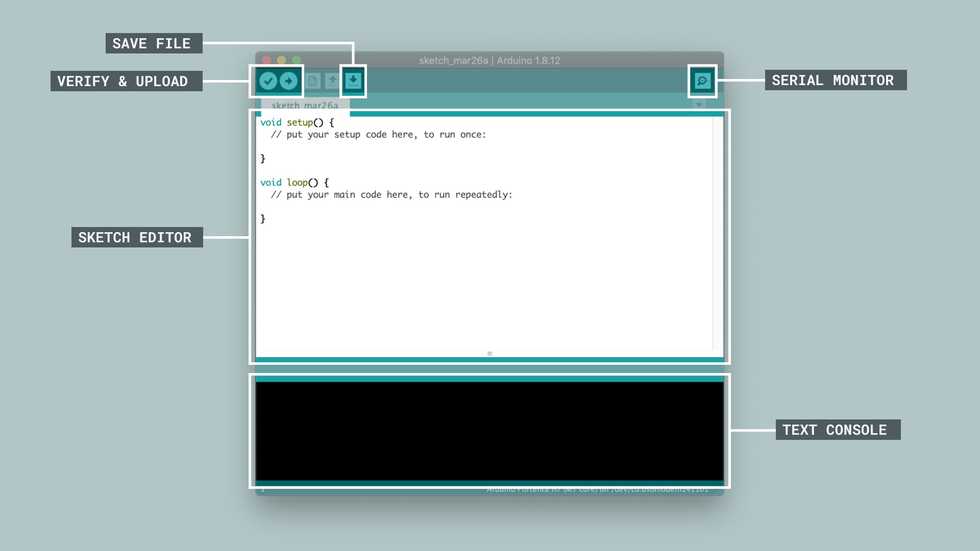
- Special functions in Sketch Editor
setup(): called once, when the sketch startsloop(): called over and over and is heart of most sketches
- Verify means compiling
Arduino Nano Motor Carrier
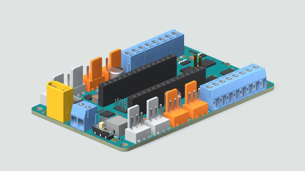
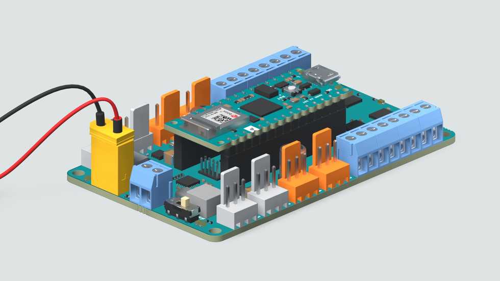
The Arduino Nano Motor Carrier is compatible with all the boards from the Arduino Nano Family
| Feature | Description |
|---|---|
| Microcontroller | ATSAMD11 ( Arm Cortex-M0+ @48 Mhz) |
| Max Input voltage (power terminals) | 4V (1S Li-Ion Battery) |
| Max output current per motor driver | 1 Amp |
| Motor driver output voltage | 12V |
| Over Temperature shutdown protection (for DC motor drivers) | Yes |
| Battery type | Li-ion battery (1S) |
| Battery charging | Yes |
| Max battery charging current | 500mA (configurable) |
| Power terminals (connectors) | XT-30 and 2POS terminal block |
| Interface | Terminal block and 3 pin/4 pin header connector |
| Servo connector | 4 terminals |
| Stepper connector | 2 terminal |
| Encoder inputs | 2 ports |
| DC motor control | 4 ports |
| 3V digital/analog sensor input/output | 4 ports |
| IMU | BNO055 9axis Accelerometer / Gyroscope/ Magnetometer |
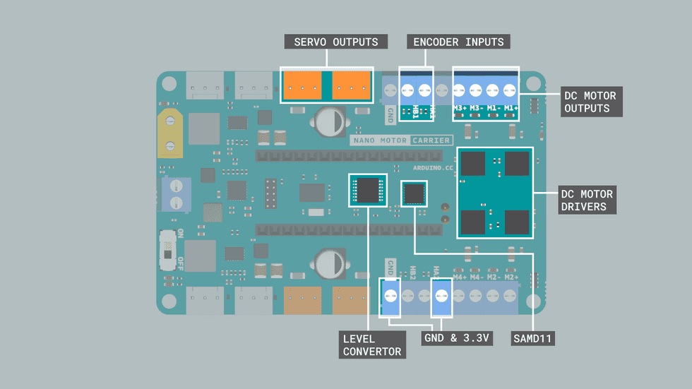
- The SAMD11 Microcontroller
- The SAMD11 is used to control the servos, read values from the encoders, and read the battery voltage in an autonomous way.
- This microcontroller receives commands and send information to the Arduino Nano 33 IoT via I2C.
- Servo Outputs
- The Servo pins handle all the communications between the servos and the Arduino Nano 33 IoT.
- Accessing the connected servos can be easily done with their corresponding Servo objects Servo1, Servo2, Servo3 and Servo4 from the IDE.
- DC Motor Outputs
- The DC motor terminal pins are used to connect any DC motor to the Carrier board.
- There are 4 terminals, M1, M2, M3 & M4, marked with a +ve and -ve sign. You can connect 4 DC motors at the same time but there are only 2 encoder inputs.
- The polarity signs signifies the direction of rotation of the connected motors.
- DC Motor Drivers
- The Motor Carrier features 4 motor drivers for high-performance DC motor control with direct connection to the Arduino Nano 33 IoT. Each driver allows you to control one DC Motor.
- The DC motors are connected to the Arduino Nano Motor Carrier using the blue connectors (terminal blocks) on each side of the board.
- The motors have to be connected in the pins that are labeled (M1+ M1-, M2+ M2-, M3+ M3- and M4+ M4-).
- Encoder Inputs
- These terminal blocks adjacent to the DC motor terminals can be used to read the encoder values from the attached DC motors through the terminals HA1-HB1 & HA2-HB2.
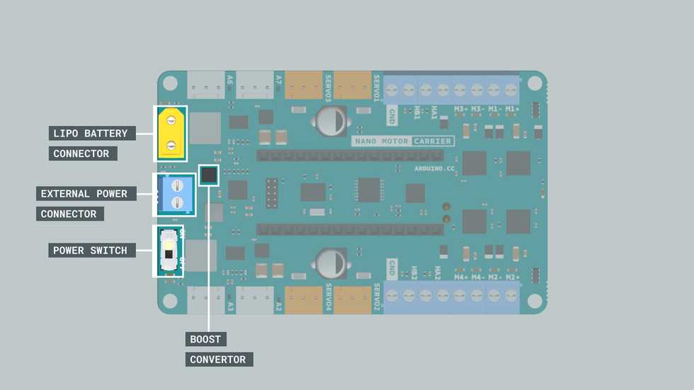
- Lipo Battery Connector
- When working with motors, you will need an external source to feed the motor drivers and power up the motors. You can do this by connecting a LiPo Battery to the battery connector.
- Boost Convertor
- A boost converter is a DC-to-DC power converter that steps up voltage from its input to its output.
- External Power Connector
- Other external power sources can be connected to the VIN input on the terminal block.
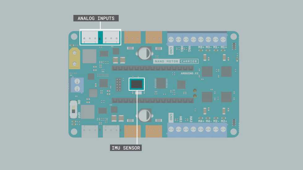
- Analog Inputs
- The carrier board also comes with 4 analog connectors used for connecting 3 pin analog sensors to the carrier board. These connectors are connected to the analog pins A2, 3, 7 and 6.
- IMU Sensor
- This carrier features the BN0055, a 9-axis (acc+gyro+magnetometer) orientation sensor.
- This IMU (Inertial measurement unit) module can measure how the carrier board behaves under changes in linear acceleration, angular rotation, and, in some cases, the magnetic field around the module.
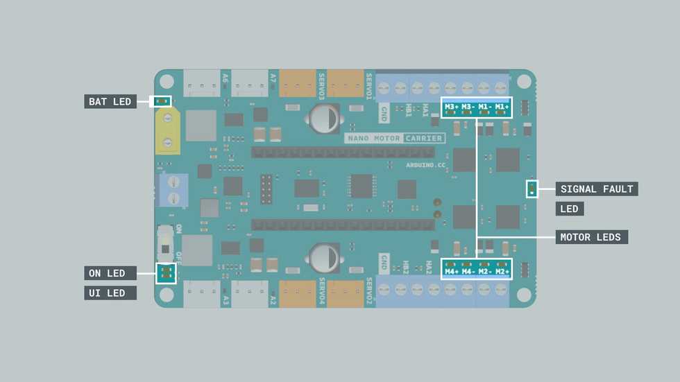
- Motor LED : This led indicates which motors are on and which directions they are spinning.
- Signal Fault LED : This lights up when there's a fault condition in the driver due to over current or over temperature.
- On LED : This LED signals when the board is powered.
- UI LED : User interface LED usually lights up when there is a problem with the library version that is incompatible with firmware version.
- BAT LED : The Battery LED Lights up when the battery is being charged.
- Plug in Nan 33 IoT to Motor Carrier.
- Some of pins will stop being available because they will be needed to control some of the features of the Carrier
- Digital pin D2 for IN2 signal for Motor3
- Digital pin D3 for IN1 signal for Motor3
- Digital pin D4 for IN2 signal for Motor4
- Digital pin D5 for IN1 signal for Motor4
- Digital pin D6 for Interrupt signal from the SAMD11 to the Arduino Nano 33 IoT
- Digital pin A4/SDA for the SDA signal (I2C)
- Digital pin A5/SCL for the SCL signal (I2C)
- to control the motors, need to import the Arduino nano Motor Carrier Library: here
- How to install library
- Some of pins will stop being available because they will be needed to control some of the features of the Carrier
- Charging the Battery
- Prerequisites:
- The Arduino Nano 33 IoT Board is connected to the Arduino Nano Motor Carrier,
- The Arduino Nano 33 IoT Board is connected to the power source via the USB,
- The power switch on the Arduino Nano Motor Carrier is On.
- Prerequisites:
Matlab
- If you want to simply execute a line of code without seeing the result in the Command Window, you can end the line with a semicolon
;. - In MATLAB, the size of a variable indicates its dimensions, in a rows x columns format.
- Variables with 1x1 as its size is called scalar;
- Vector is one-dimentional array.
v1 = [1 3 2 6 4 4 9]creates vector of one rowv2 = [2;5;7;1;2]creates vector of one column
- You can reorient a vector as a column or row using the transpose operator (
'):v2 = v2' - vector can be generated by
({start}:{step}:{end}) - Vectorization is a key feature of the MATLAB language, and it allows you to write simple, concise lines of code that execute many operations at once, and which closely resemble mathematical expressions.
arduinosetupto load necessary library into Arduino boarda = arduinoto establish the connection with Arduino Nano 33 IoT
Simulink
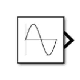
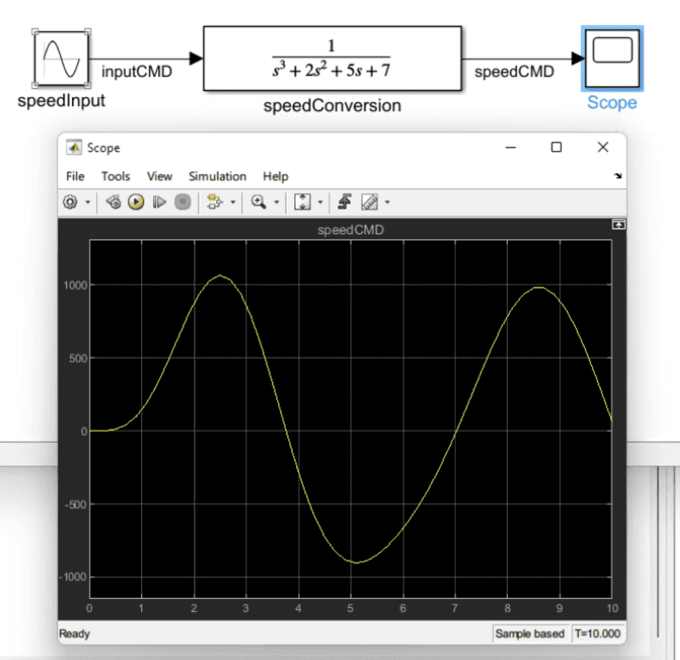
- Source > Sine Wave: a block functions as signal source
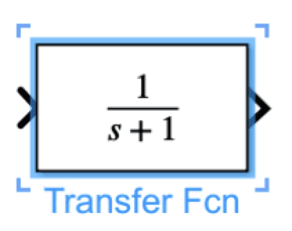
- Continuous > Transfer Fcn: a block that continuously modifies that signal
- Sink > Scope:
- Notice that these blocks generally have an inward triangular port on their left, known as an import
- Block imports allow you to Terminate a signal.
- Connected these 3 blocks:
- Configurations can be applied by double clicking the blocks
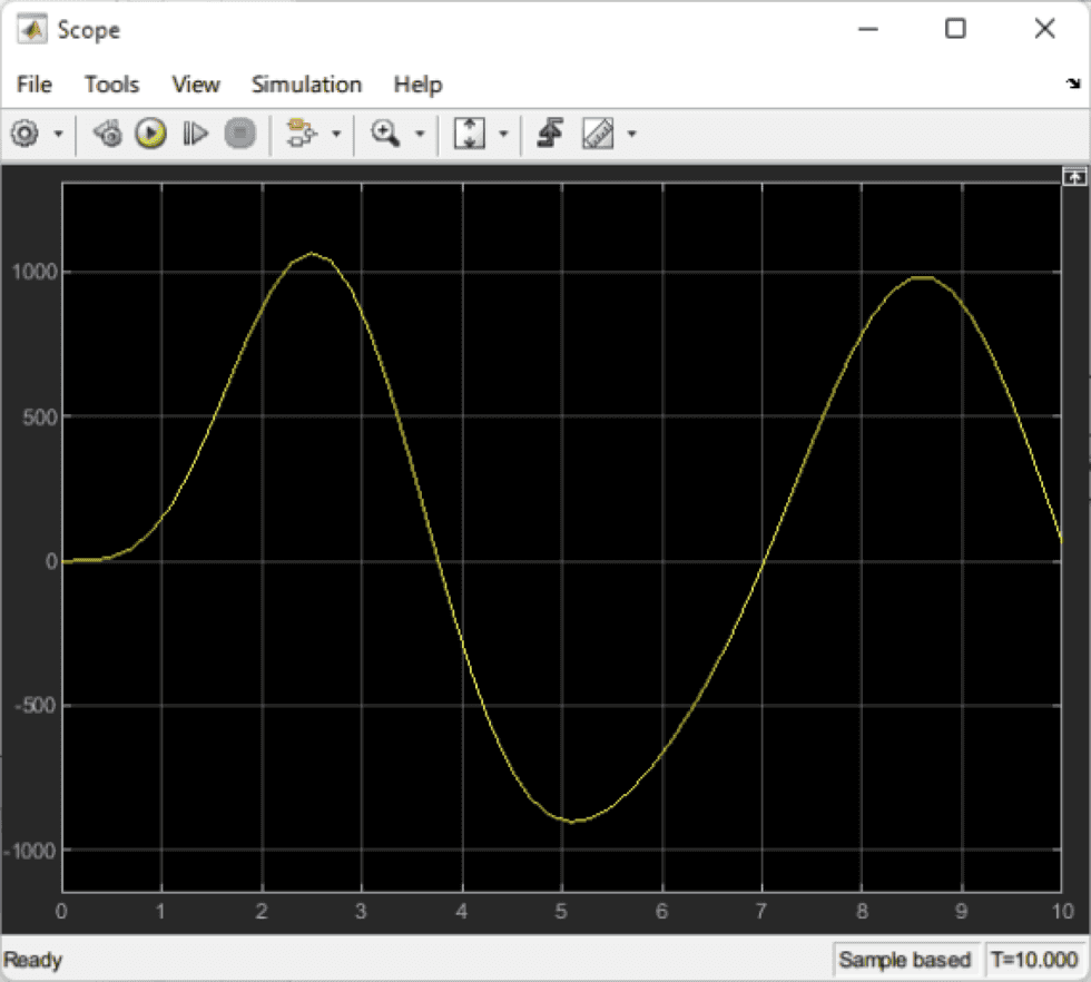
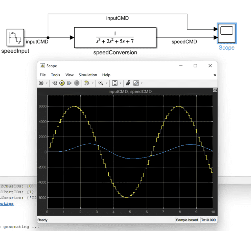
- "Run" and we can see the output by double clicking Scope
- Blocks and Links can be labeled
- Currently, this simulation is running in continuous mode. Soon you will upload and run this algorithm on the Arduino board, which executes in discrete time. We need to adjust the model to simulate in discrete time so that we understand how it will work on the Arduino Nano 33 IoT board later.
