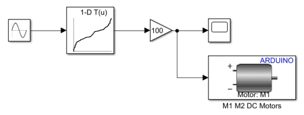
Create the Blocks
- "Sine Wave" to simulate the speed input.
- "1-D Lookup Table" to convert the user's speed signal comming from the Sine Wave block into a PWM signal between -1 and 1.
- "Gain" block to multiplies a Simulink signal by a constant value.
- "Scope" block to visulize the output.
Configure the Blocks
load motorResponseto load the previous saved speedMono and PWMcmdMono- We can see that the RPM is around 300. Then we configure the "Sine Wave" block as
amplitude-300, frequency-0.2 - To configure the "1-D Lookup Table", we set Table data to PWMcmdMono and set Breakpoints to speedMono.
- "Gain" block: Amplify the PWM duty cycle to cover a range of -100 to 100, to be compatible with the motor driver later. Double-click the Gain block and set Gain to 100. Then click OK:
- To access the motor connected to the Arduino Nano Motor Carrier you need an Arduino Device Driver block.
Deploy the Model to Arduino
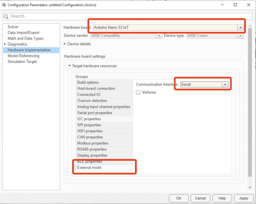
- MODELING > Model Settings:
- Then, HARDWARE > Monitor & Tune: to build an executable and upload to hardware.
Note: change the baud rate to 9600.


